| The Autonerdz Community Forums | |
|
https://yabb.autonerdz.com/cgi/yabb2//YaBB.pl
>> >> 2 wire AC signal normal orientation https://yabb.autonerdz.com/cgi/yabb2//YaBB.pl?num=1575651659 Message started by Reedvalve on Dec 6th, 2019 at 9:00am |
|
|
Title: 2 wire AC signal normal orientation Post by Reedvalve on Dec 6th, 2019 at 9:00am
Im sure I have heard Tom or someone discuss this in all the audio I have ect. Could someone remind me, what is the normal orientation of a two wire ac signal. In other words, can I quickly identify a sensor thats wired backwards? I'm assuming that would have an impact on what the ecm expects? Myron
|
|
Title: Re: 2 wire AC signal normal orientation Post by Tom Roberts on Dec 6th, 2019 at 10:24am
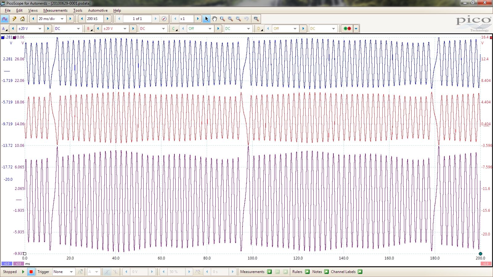
Two main types of VR CKP styles.
Non floating: Has a signal on only one wire. Zero volts is center of waveform. Floating: Has a signal on both wires and 'floats' above zero when you have the channel grounded to B neg. Here is a floating EDIS CKP example with CKP pos on A, CKP neg on B and A-B math. When looking at things like CKP/CMP timing and using the CKP for a reference to measure, we want CKP pos. Telling if the sensor is wired backwards would not necessarily be apparent with the scope trace as you would still have two wires with opposite waveforms. They would be on the wrong wire colors/terminals though. edisckp.jpg (900 KB | ) |
|
Title: Re: 2 wire AC signal normal orientation Post by Reedvalve on Dec 8th, 2019 at 10:59am
Thanks Tom. Do we know what part of the waveform the pcm is looking for? I assume it’s not concerned with amplitude as long as the amplitude meets a certain threshold? In the case of a 2 wire floating ground VR sensor, with wires flipped, if the pcm is only looking at the switch point across the zero point, then wires being crossed would not change the timing, but if pcm is looking at a different part of the wave, then a switched wire VR would throw the timing of the sensor out of phase. Correct?
|
|
Title: Re: 2 wire AC signal normal orientation Post by rayray on Dec 8th, 2019 at 2:48pm
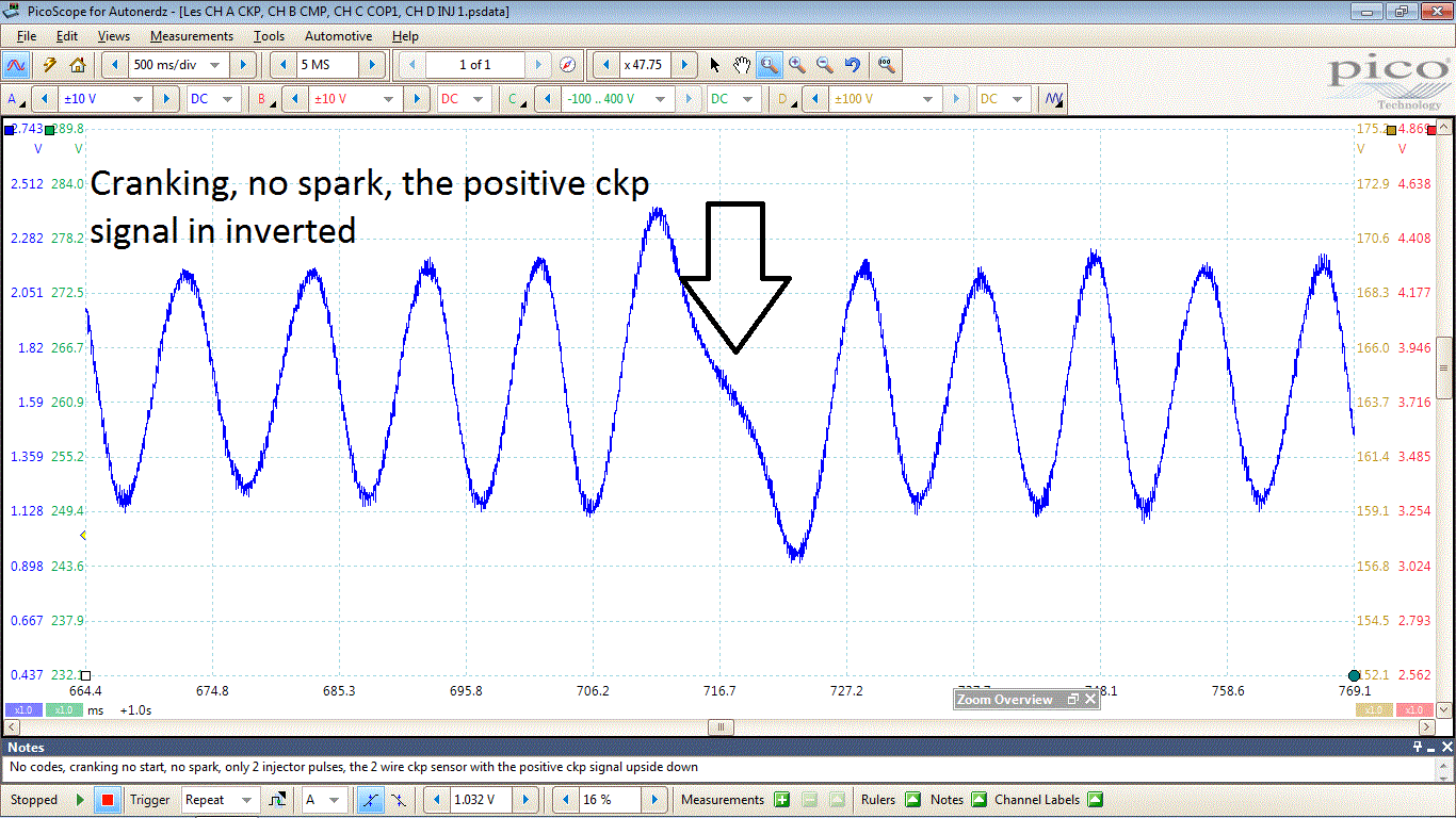
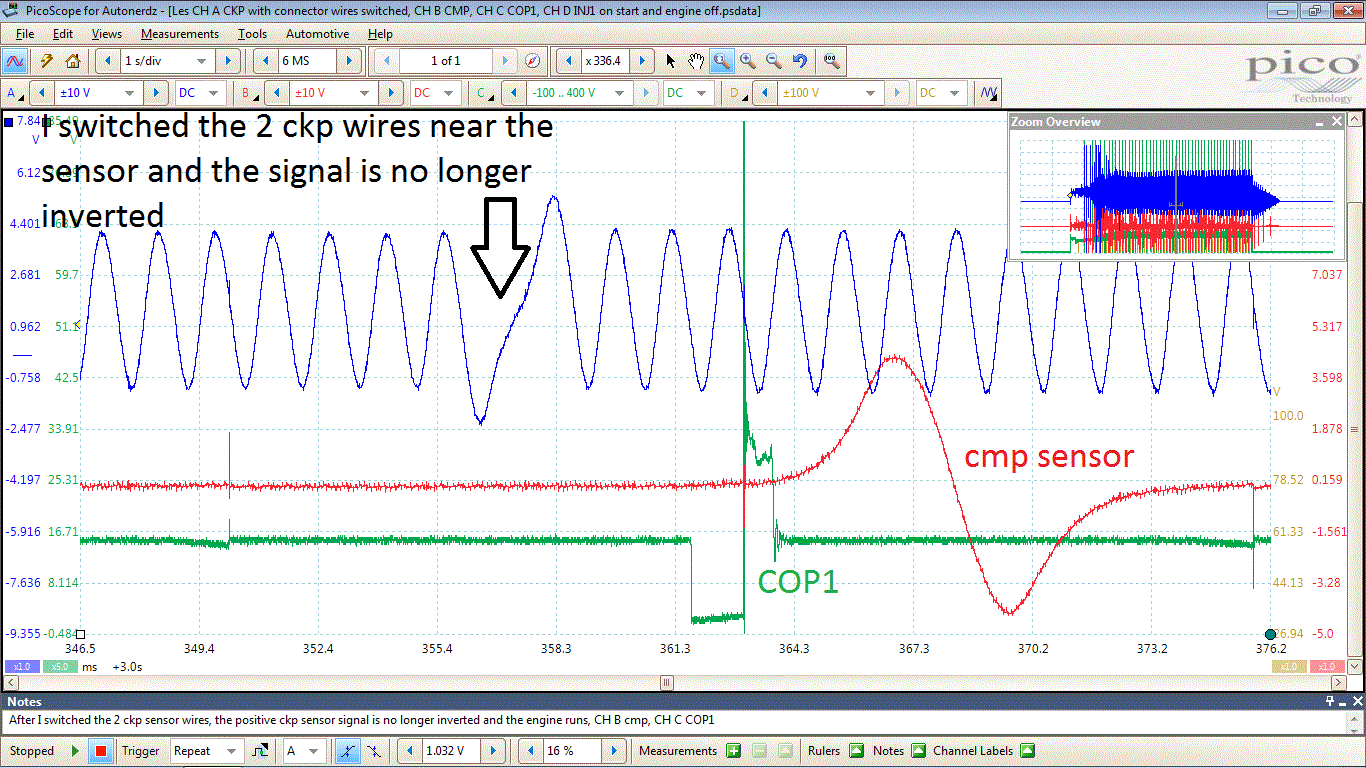
The PCM is looking at the shape of the missing reluctor tooth/air gap voltage, in the positive ckp signal.
In the first GIF, the missing reluctor tooth/air gap positive voltage is upside down or inverted. On this Lincoln, there was no spark and only 2 injector triggers. In the second GIF I switched the 2 ckp wires and the positive ckp signal is no longer inverted. The engine now starts and runs. 98_Lincoln_Town_Car_4_6_no_codes__cranking_no_start__no_spark__only_2_injector_triggers__the_ckp_sensor_positive_signal_is_inverted.gif (118 KB | ) 98_Lincoln_Town_Car_4_6_I_switched_the_2_ckp_wires_near_the_sensor_and_the_positive_ckp_signal_is_no__longer_inverted__CH_B_cmp_sensor__CH_C_COP1_and_running.gif (138 KB | ) |
|
Title: Re: 2 wire AC signal normal orientation Post by Reedvalve on Dec 8th, 2019 at 4:45pm
Thanks Ray, very helpful.
|
|
Title: Re: 2 wire AC signal normal orientation Post by Spence on Dec 8th, 2019 at 5:10pm rayray wrote on Dec 8th, 2019 at 2:48pm:
Pretty cool rayray. I had one come in that did run with the CKP wires switched. It does change the ignition time. Crazy one to figure out what the hell was going on! :D Does make it stick in your head and want to see the captures correct though. 8-) |
|
Title: Re: 2 wire AC signal normal orientation Post by Ford racer on Dec 10th, 2019 at 6:36pm
I'm very curious as to why the ckp wires would ever get switched? I've never seen that or ever heard of that happening. Someone messing with them? If so, why?
|
|
The Autonerdz Community Forums » Powered by YaBB 2.5 AE! YaBB Forum Software © 2000-2010. All Rights Reserved. |