The Autonerdz Community Forums
https://yabb.autonerdz.com/cgi/yabb2//YaBB.pl
>> >> Cranking Compression waveform
https://yabb.autonerdz.com/cgi/yabb2//YaBB.pl?num=1482523491

Message started by James H on Dec 23rd, 2016 at 12:04pm

Title: Cranking Compression waveform
Post by James H on Dec 23rd, 2016 at 12:04pm
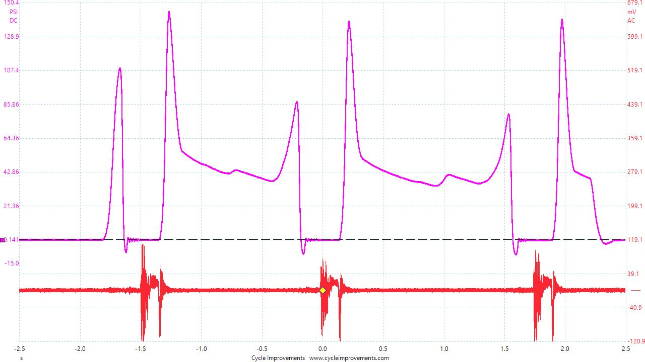
This is a cranking compression waveform from a Suzuki DRZ400. I am trying to understand why it looks like this. The valve clearance was out, the 1 exhaust bucket and cam lobe is badly worn so obviously the valve timing is out. The engine was turning over very slowly and uneven as the starter is just about baked as well. I do not understand how it can have 2 peaks. It looks like the exhaust valves were not opening but they are, Any thoughts?
Suzuki_DRZ400SM_2006_1.jpg (91 KB | )

Title: Re: Cranking Compression waveform
Post by Mick on Dec 23rd, 2016 at 7:38pm

James H wrote on Dec 23rd, 2016 at 12:04pm:
the 1 exhaust bucket and cam lobe is badly worn


If the exhaust cam lobe is worn to the extent that the valve  is only opened for a short time the piston is still rising and against a sealed cylinder until the intake opens. IF the INTAKE opend at all.

Did you use the WPS500 psi range 1 in the library?

I wonder if the psdata file would help us here? :-/


Title: Re: Cranking Compression waveform
Post by RedlinePowersports on Feb 13th, 2017 at 6:55pm
Does the DRZ have a decompression valve? New to picoscopes but that may be your second peak.

Title: Re: Cranking Compression waveform
Post by busjockey on Feb 14th, 2017 at 10:23am
James put your capture up so we can all take a look. :)

Title: Re: Cranking Compression waveform
Post by James H on Feb 14th, 2017 at 2:48pm
Here you are. A little history. Bike was brought in mostly disassembled for a valve adjustment only and I did an in cyl compression check before I took the valve cover off. - Bike had no flywheel pickup or stator, ign coils, cdi etc, as customer was doing some work on it.  ::) basically just the starter as far as electrical which was also on its last legs. So I couldn't reference the comp waveform to anything. It is really just a curiosity as to why it look like it does as the problems were obvious and have been addressed other than I am still waiting for cams.
https://yabb.autonerdz.com/cgi/yabb2//YaBB.pl?action=downloadfile;file=Crank_Comp___FL_Intake.psdata (6311 KB | )

Title: Re: Cranking Compression waveform
Post by RedlinePowersports on Feb 14th, 2017 at 9:08pm
I looked up spec for compression on that bike, looks like it is supposed to be about 135psi. Looks like on your waveform that it is coming in around 144psi. Not really far off considering you said you have an exhaust bucket sticking which will make it hard for exhaust gases to get out.

Still not sure why you have two peaks but I am interested to see what this form looks like after you put your new cams in.

Title: Re: Cranking Compression waveform
Post by busjockey on Feb 15th, 2017 at 5:44am
Sorry, don't know bikes.  Is this a four stroke engine?  Could you post up some system operation? :)

Title: Re: Cranking Compression waveform
Post by busjockey on Feb 15th, 2017 at 5:53am
Hey I tried to look at the capture and I have the latest software.  Did you use the beta for this capture?  My Pico said it doesn't have the latest software. :)

Title: Re: Cranking Compression waveform
Post by James H on Feb 15th, 2017 at 7:33am
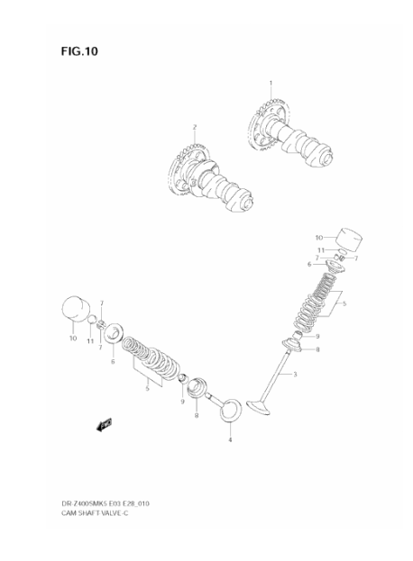
Yes, it was the Beta software. It is a single cylinder 4 Stroke double overhead cam 4v engine. Cams operate the valves via a bucket and shim arrangement. Had a decompression release but had been removed as they were aftermarket cams.
valves.png (41 KB | )

The Autonerdz Community Forums » Powered by YaBB 2.5 AE!
YaBB Forum Software © 2000-2010. All Rights Reserved.